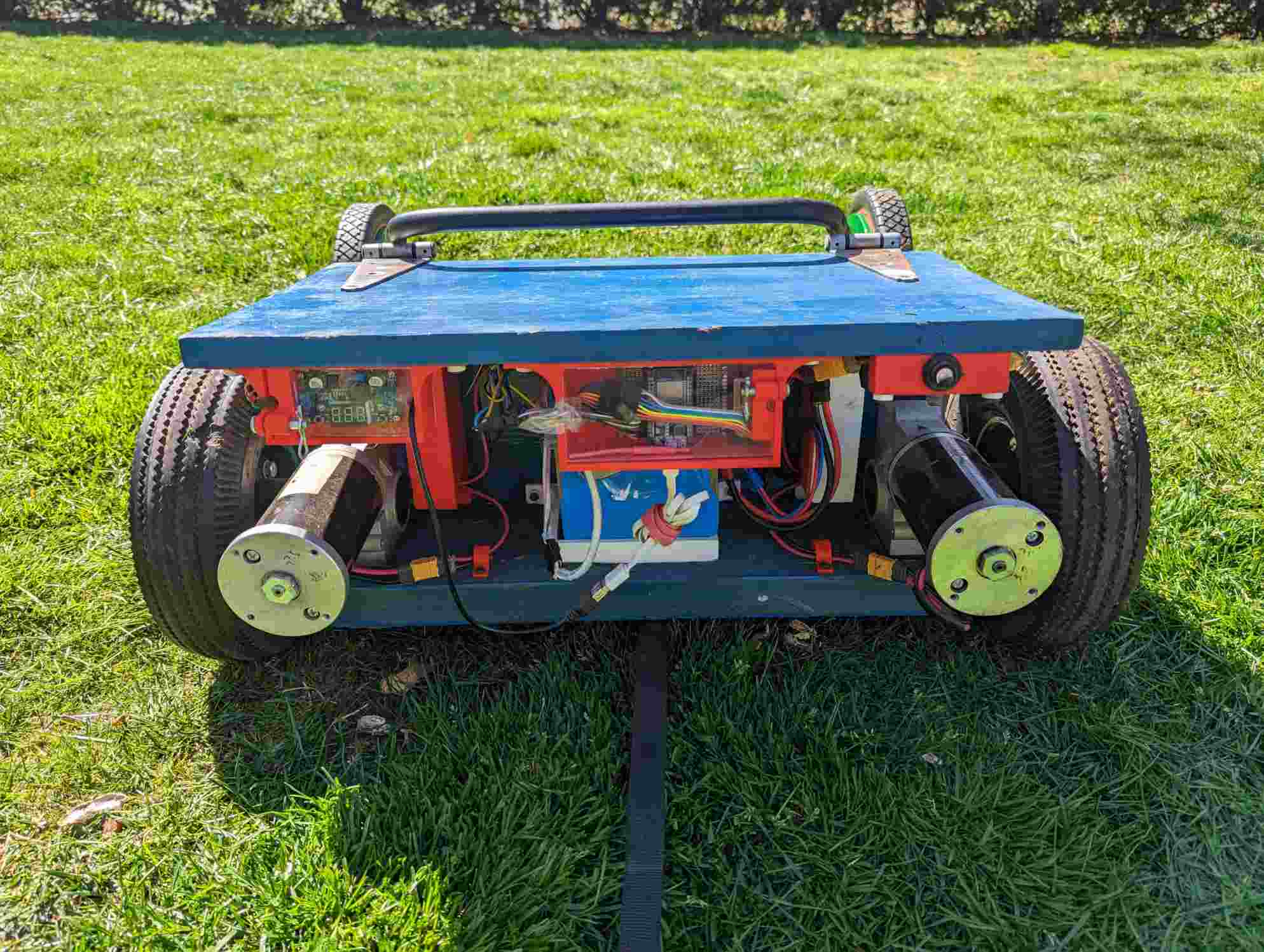
Remote Controlled Lawn Mower
This post is about a remote controlled lawn mower I created!
Remote Control Lawn Mower Project:

Introducing phase one of the autonomous lawn mower project! A remote controlled lawn mower/rover/platform!
Motivation
I hate doing repetitive tasks. Cutting the grass is one of those tasks that I really wish I never had to do again. Working landscaping jobs over many summers, I have cut multiple lifetimes worth of grass. I am over it. Through those many hours I often have contemplated automating the task, and I finally set forth to do it.
I decided to break this project into two phases. In phase one, I wanted something very achievable, and to make grass cutting fun. Phase two would be the ultimate desire.
Phase 1: Create a remote controlled lawn mower
Phase 2: Make it autonomous
Phase 1 is covered here. Phase 2 is to be implemented at a later date (hopefully). The rough concept for phase 2 is to use differential gps and inertial sensors, along with rover control and mission planning software, that enable the mower to operate autonomously following preplanned routes.
Side note:
The mower is actually a rover/mower combo because it is intended to be a generic platform that anything can attach to, but the main use will be a reel mower attachment. I’m not sure If I started off with the concept of disassociating the mower from the platform, but as I was building, it became very evident that it should definitely be decoupled. One of these days I’m going to attach the rover to a wagon and pull my niece around.
Constraints
There were two key constraints of this project that took consideration over everything else:
- It should be safe. From both the mower, to the battery, to the redundant safety devices in between.
- It should be as cheap as possible, without sacrificing safety. This included R&D costs.
There was much work put into researching components and designing systems before any money was put into the project. Naturally of course, even with all this prep work, there were many costly iterations. See motor section and lessons learned section for more details.
In all the attempts to de-risk the project the scariest part was not knowing if any of it was actually going to come together and work. I mean I was hopeful it would and probably should in concept but I was never fully sure until everything was integrated and I tested it. In theory I ought to be able to push a reel lawn mower with wheelchair motors, right? It should be capable of turning even with fixed wheels, right? The battery should probably be able to deliver enough power to function, right? And last at least 45 minutes, right? Etc.
And to my delight it all worked! I was over the moon seeing it cut for the first time, and it was such a huge relief! A demonstration can be seen below. One thing I certainly wasn’t expecting was how cool it would sound!
User Guide
I even made a user guide/checklist for my own benefit and to allow others to use it in my absence. The user guide can be found here.
High level design overview
The most interesting part of this work for others is probably the high level architectural design. A block diagram is shown below.
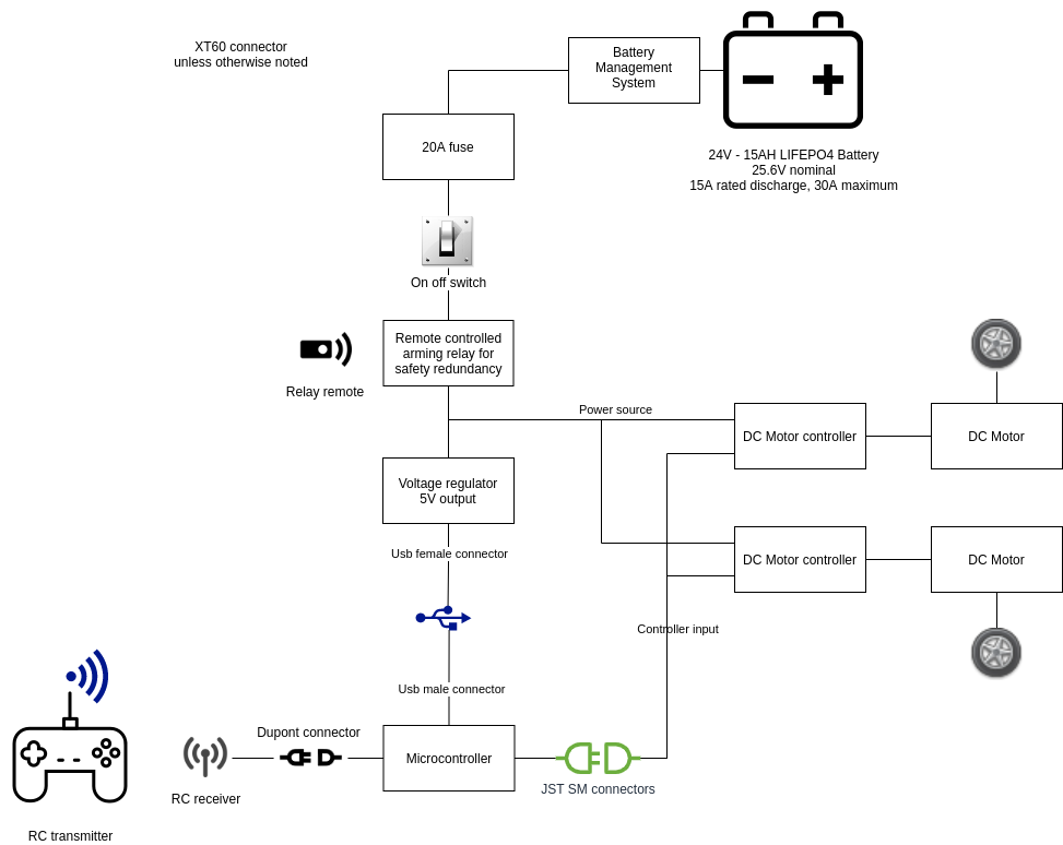
In the diagram you can see the battery being the main source of power. Then, the battery goes through a fuse, for safety, followed by a power toggle switch and independent remote arming switch. Then there’s the motor drivers and DC motors which are attached to the wheels.
There’s also a voltage regulator to drop the battery voltage to 5V for the microcontroller. The microcontroller powers and reads the RC receiver. Most importantly, it interprets the input coming from the receiver and signals the motor drivers to control the motors.
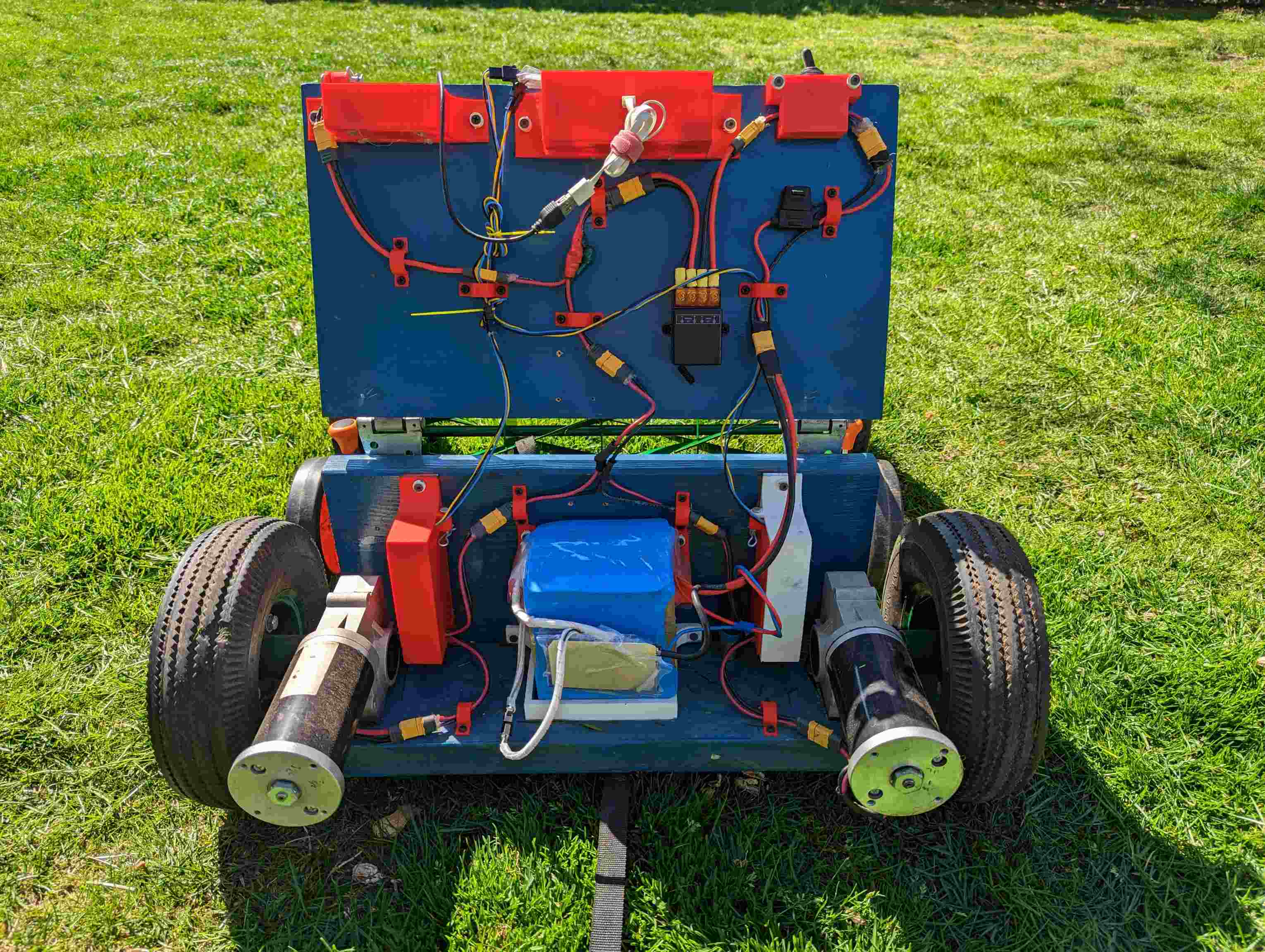
If you look closely you should be able to map everything from the block diagram above to the opened rover shown below.
Code
This microcontroller program can be seen here along with the wiring diagram found here.
This code is intended to be run on an ESP32 and uses the Arduino IDE. As mentioned earlier, it interprets the signal from the receiver, and intelligently translates that to signal the motor drivers. There is also a smoothing function that was implemented to enhace the driving experiance, and eliminate harsh instantanteous torques on the system.
The controller works on both a direct drive, dual stick tank type mode, with one stick controlling one wheel, and a single stick drive mode that takes more interpretation. The modes can be switched by hitting a toggle switch on the controller. An example of the driving modes can be seen in the video below.
Components
- Battery: Ping Battery- LiFePO4 24V, 15Ah Battery ($350 shipped with charger) (looks like they’re out of business)
- Motors: Jazzy - Used DC Wheelchair Motors ($35 x2 motors)
- Motor Drivers: Cytron - 20A, 6-30V DC Motor Driver ($20 x2)
- Remote Switch: dstfuy Wireless Remote Switch DC ($24)
- Microcontroller: ESP32 (any microcontroller will do I just had a spare lying around)
- Voltage Regulator: LM2596 adjustable (there are many) (~$3)
- Plugs: XT60 connectors, 12 gauge stranded wire, JST SM connectors
- Wheels: Scavenged split rim wheels x2
- Transmitter - Used FlySky T6, 6 channel (~$25)
- Receiver - Used FlySky R6B, 6 channel ( ~$10)
- Power usage monitor (optional): bayite Power Monitor ($18)
- Conformal coating - MG Chemicals 442C ($12)
- Fuse - 20A car fuse from a pack
Components in depth
Battery

The first and arguably most important component that needed to be selected was the battery. This took the longest to research. I was very concerned with battery safety so grabbing old 18650 lithium-ion cells and strapping them together wasn’t going to cut it. Also, being the most expensive component, price played an important secondary constraint as well. Ultimately, I decided to go with a LiFePO4 battery. This chemistry was chosen because it is widely considered to be among the safest. It has beneficial properties that make it more resistant to ignition or thermal runaway, give it the ability for high current ratings, and provide better structural integrity than other chemistries. Additionally, it can handle many deep cycle discharges, delaying fears of costly required replacement, or anxious monitoring of the battery level. I sourced my battery from pingbattery.com, and chose the 24V, 15Ah battery. Some napkin calculations predicted I should get decently over 45 minutes of runtime with the battery, which was the minimum considered before battery charging would get in the way of grass cutting.
The technical specifications of the battery can be found at the bottom of the user guide.
Pingbattery.com appears to be offline these days after over a decade of business but data is still accessible from the internet archive.
The ping batteries were great due to their size, as they are intended to be put on e-bikes and e-scooters, but in the future I would also consider a LiFePo4 battery in the form factor of a 12-Volt lead acid car battery. That should be a little cheaper, and have a more rugged build, at the cost of space and weight.
I accidentally killed two of the eight battery cell packs while leaving the Battery Management System (BMS) connected over the course of several months. I reached out to Ping and was able to diagnose, purchase, and replace the dead cell packs. Replacing the cell packs was not a fun experience.
Motor/Motor Driver
The motor and motor drivers were the most frustrating part of this project. I needed something that could push a reel mower, without having any idea how much force a reel mower took to push. And I wanted to do it without breaking the bank.
Whereas most brushless DC (BLDC) motors were designed to be low torque and very high RPM, hoverboard motors were the opposite. Moreover, these motors integrated the wheel directly into the motor, which reduced the number of components and eliminated the need for any coupling mechanism. Additionally, due to the proliferation of hoverboards, they could be obtained secondhand for a cheap price. I purchased a pair for $35!
And then got a pair of BLDC motor controllers that are very similar to this:
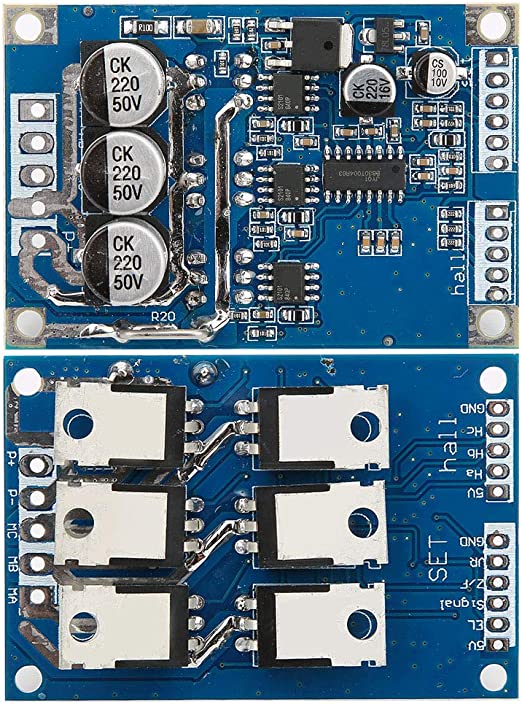
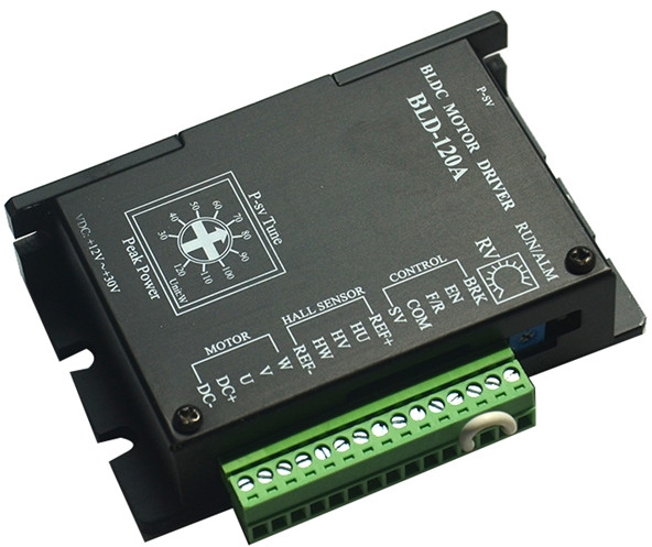
And when I soldered it up and programmed a controller for it I got very inconsistent results. The motor would frequently fail to start. Additionally it would pretty much only start at high speed. Not much of an option for a lawn mower. And hoverboards themselves spend much of the time slowly inching forwards so the motor wasn’t a poorly chosen component. So I tried another motor driver, a “BLD-120A”, which also exhibited similar kinds of issues. It looks like this:
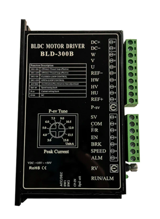
Then I tried a final motor driver, a “BLD-300B” which was similar, but more capable. I also invested in a 36V power supply to ensure the motors were receiving adequate power. And with this last motor driver the motors still failed to start consistently. These motor drivers look like this:
The way I saw it there were three paths ahead.
- Buy an ODrive (~$150+) motor driver which is reputable and has explicit instructions for use with hoverboard motors
- Design and create my own motor driver
- Try a different type of motor.
The first option seemed excessively priced, and too sophisticated for the requirements.
I nearly did the second one but didn’t want to sink too much time on a tangent.
And so a new component appeared like the best option. The ideal choice would be a motor with simple DC controls. Further research led me to wheelchair motors, which may not have the same speed as hoverboard motors, but since they were originally designed for wheelchairs, they should have sufficient speed and torque. Moreover, the best part about these motors is that they have straightforward DC controls.
I purchased two used motors to test, and they were fantastic! I directly connected the motors to a power source and they started turning no problem.
With the motors sorted out, I procured drivers capable of handling the power capacities of the motors, which is approximately 250w per motor. The drivers I got are capable of up to 20A at 30V and look like this:
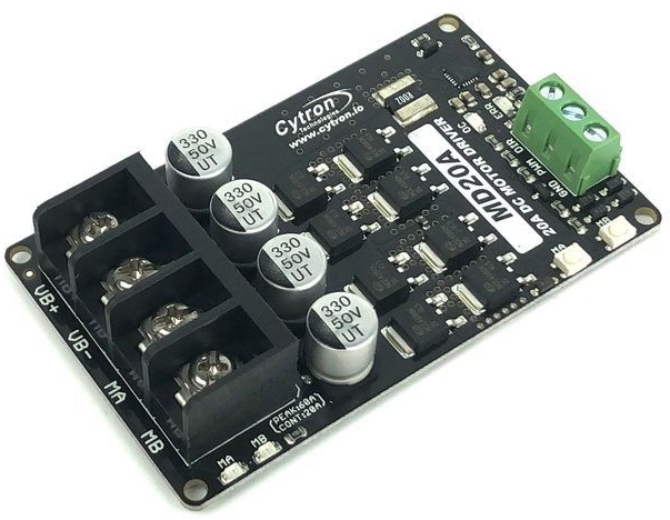
And as expected with DC motors, these worked like a charm.
Motor to wheel coupling
The next big issue was coupling the motor shaft to some wheels. The motors have keyed shafts but came without a key. So after many different 3D printing designs and broken key prototypes I was able to get a metal key that fit. Then I cut washers to fit over the key and shaft, and had those welded onto the wheels. This proved to be a worthy coupling mechanism. The biggest take away I got from this was to keep 3D prints modular. By integrating the key directly into the coupling mechanism, the entire print was rendered worthless when the key failed - a setback that could have been avoided with a more modular approach.
3D modeling:
For designing the 3d models I turned to openSCAD for the first time. OpenSCAD allows you to model with code, and because it’s code you can make everything parameterizable which is an asset when you’re trying to dial in really tight tolerance parts. I found it to be a joy to use and highly recommend it!
The most intense printing was done to attempt the motor to wheel coupling mechanism which ultimately was scrapped. However, many other prints were made that were utilized. Mostly, each of the different PCBs had their own housing which allowed them to be mounted to the rover. The design was reused, but custom fit for each board, which was simple to do with the parameterization openSCAD offers. The design provided mounting holes for the board to attach to the housing, as well as a protective cover with a quick release mechanism for easy access. The models can be seen below.
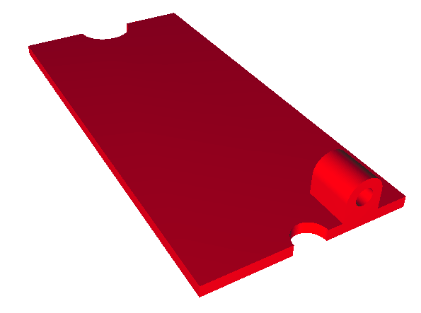
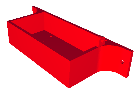
Some of the OpenSCAD, stl, and gcode files can be found here.
Driving experience
I’ve been fortunate enough to use the mower quite a bit and have to say, it excites the hell out of me every time! The controls needed some tuning as the used motors were not very equivalent, and a quick code patch did wonders! Now straight lines are a breeze. The rigid nature of the wheels on the reel mower makes pivoting in place difficult. It takes some practice to avoid those situations. Most significantly, when the mower is not facing the same direction as you’re facing it can melt your mind trying to control it. I added a toggle to flip which direction is considered forward so it is easier to control when it’s coming at you. It’s cool to be able to update your own design so easily.
Contemplating further improvements, I selected components for a cheap First Person View (FPV) setup, which would allow forward to always be forward. However, I have not yet made that investment.
The cutting actually comes out great as well! The edges may need some touch up afterwards, but it works much better than anticipated and is a real viable alternative to cutting the grass! Overall I am quite thrilled with how everything turned out!
Lessons learned
-
The fuse should be the very first thing in the circuit so nothing can escape its path. If not it’s leaving room for a potential unprotected short. I learned this the hard way when a wire slipped and caused sparks to fly but the fuse didn’t blow. I was confused at first but later made the realization the short happened outside of the path of the fuse. The fuse should go first!
-
When the fuse keeps popping, critically assess the situation before upping the fuse rating. I had the motor driver plugged in backwards and it was back powering the system. Thankfully the fuse was able to save the situation, until I upped the rating and fried the mcu and receiver. Wow, did I feel dumb.
-
Double check your connector mating is accurate, and maybe use different connector types to make it more obvious. Without noticing, I installed the motor driver power input with a male end when it should have been female, and the driver output with a female end when it should have been male. A simple mistake, especially with screw terminals on the board side. This had me back powering the board leading to the failure above.
-
Ferrule is used to hook wires to screw terminals. They work fantastically well.
-
I found an excellent crimping guide, and guide to common JST connectors. https://iotexpert.com/jst-connector-crimping-insanity/ If it for some reason disappears I recommend using the internet archive to find it.
-
Double check the specs on the conformal coating because it’s pretty easy to get the wrong one.
